2. Genesis
3. The Screen
4. The GDT and IDT
5. IRQs and the PIT
6. Paging
7. The Heap
8. The VFS and the initrd
9. Multitasking
10. User Mode
5. IRQs and the PIT
In this chapter we're going to be learning about interrupt requests (IRQs) and the programmable interval timer (PIT).
5.1. Interrupt requests (theory)
There are several methods for communicating with external devices. Two of the most useful and popular are polling and interrupting.
Polling
Spin in a loop, occasionally checking if the device is ready.
Interrupts
Do lots of useful stuff. When the device is
ready it will cause a CPU interrupt, causing your handler to be run.
As can probably be gleaned from my biased descriptions, interrupting is considered better for many situations. Polling has lots of uses - some CPUs may not have an interrupt mechanism, or you may have many devices, or maybe you just need to check so infrequently that it's not worth the hassle of interrupts. Any rate, interrupts are a very useful method of hardware communication. They are used by the keyboard when keys are pressed, and also by the programmable interval timer (PIT).
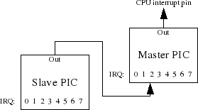
The slave's output is connected to IRQ2 of the master.
The other clever thing about the PIC is that you can change the interrupt number it delivers for each IRQ line. This is referred to as remapping the PIC and is actually extremely useful. When the computer boots, the default interrupt mappings are:
- IRQ 0..7 - INT 0x8..0xF
- IRQ 8..15 - INT 0x70..0x77
5.2. Interrupt requests (practical)
The PICs are communicated with via the I/O bus. Each has a command port and a data port:
- Master - command: 0x20, data: 0x21
- Slave - command: 0xA0, data: 0xA1
{
...
// Remap the irq table.
outb(0x20, 0x11);
outb(0xA0, 0x11);
outb(0x21, 0x20);
outb(0xA1, 0x28);
outb(0x21, 0x04);
outb(0xA1, 0x02);
outb(0x21, 0x01);
outb(0xA1, 0x01);
outb(0x21, 0x0);
outb(0xA1, 0x0);
...
idt_set_gate(32, (u32int)irq0, 0x08, 0x8E);
...
idt_set_gate(47, (u32int)irq15, 0x08, 0x8E);
}
Notice that now we are also setting IDT gates for numbers 32-47, for our IRQ handlers. We must, therefore, also add stubs for these in interrupt.s. Also, though, we need a new macro in interrupt.s - an IRQ stub will have 2 numbers associated with it - it's IRQ number (0-15) and it's interrupt number (32-47):
; the IRQ number, the second is the ISR number it is remapped to.
%macro IRQ 2
global irq%1
irq%1:
cli
push byte 0
push byte %2
jmp irq_common_stub
%endmacro
...
IRQ 1, 33
...
IRQ 15, 47
We also have a new common stub - irq_common_stub. This is because IRQs behave subtly differently - before you return from an IRQ handler, you must inform the PIC that you have finished, so it can dispatch the next (if there is one waiting). This is known as an EOI (end of interrupt). There is a slight complication though. If the master PIC sent the IRQ (number 0-7), we must send an EOI to the master (obviously). If the slave sent the IRQ (8-15), we must send an EOI to both the master and the slave (because of the daisy-chaining of the two).
First our asm common stub. It is almost identical to isr_common_stub.
[EXTERN irq_handler]
; This is our common IRQ stub. It saves the processor state, sets
; up for kernel mode segments, calls the C-level fault handler,
; and finally restores the stack frame.
irq_common_stub:
pusha ; Pushes edi,esi,ebp,esp,ebx,edx,ecx,eax
mov ax, ds ; Lower 16-bits of eax = ds.
push eax ; save the data segment descriptor
mov ax, 0x10 ; load the kernel data segment descriptor
mov ds, ax
mov es, ax
mov fs, ax
mov gs, ax
call irq_handler
pop ebx ; reload the original data segment descriptor
mov ds, bx
mov es, bx
mov fs, bx
mov gs, bx
popa ; Pops edi,esi,ebp...
add esp, 8 ; Cleans up the pushed error code and pushed ISR number
sti
iret ; pops 5 things at once: CS, EIP, EFLAGS, SS, and ESP
Now the C code (goes in isr.c):
void irq_handler(registers_t regs)
{
// Send an EOI (end of interrupt) signal to the PICs.
// If this interrupt involved the slave.
if (regs.int_no >= 40)
{
// Send reset signal to slave.
outb(0xA0, 0x20);
}
// Send reset signal to master. (As well as slave, if necessary).
outb(0x20, 0x20);
if (interrupt_handlers[regs.int_no] != 0)
{
isr_t handler = interrupt_handlers[regs.int_no];
handler(regs);
}
}
This is fairly straightforward - if the IRQ was > 7 (interrupt number > 40), we send a reset signal to the slave. In either case, we send one to the master also.
You may also notice that I have added a small custom handler mechanism, allowing you to register custom interrupt handlers. This can be very useful as an abstraction technique, and will neaten up our code nicely.
Some other declarations are needed:
5.2.1. isr.h
#define IRQ0 32
...
#define IRQ15 47
// Enables registration of callbacks for interrupts or IRQs.
// For IRQs, to ease confusion, use the #defines above as the
// first parameter.
typedef void (*isr_t)(registers_t);
void register_interrupt_handler(u8int n, isr_t handler);
5.2.2. isr.c
void register_interrupt_handler(u8int n, isr_t handler)
{
interrupt_handlers[n] = handler;
}
And there we go! We can now handle interrupt requests from external devices, and dispatch them to custom handlers. Now all we need is some interrupt requests to handle!
5.3. The PIT (theory)
The programmable interval timer is a chip connected to IRQ0. It can interrupt the CPU at a user-defined rate (between 18.2Hz and 1.1931 MHz). The PIT is the primary method used for implementing a system clock and the only method available for implementing multitasking (switch processes on interrupt).
The PIT has an internal clock which oscillates at approximately 1.1931MHz. This clock signal is fed through a frequency divider, to modulate the final output frequency. It has 3 channels, each with it's own frequency divider.
- Channel 0 is the most useful. It's output is connected to IRQ0.
- Channel 1 is very un-useful and on modern hardware is no longer implemented. It used to control refresh rates for DRAM.
- Channel 2 controls the PC speaker.
Channel 0 is the only one of use to us at the moment.
OK, so we want to set the PIT up so it interrupts us at regular intervals, at frequency f. I generally set f to be about 100Hz (once every 10 milliseconds), but feel free to set it to whatever you like. To do this, we send the PIT a 'divisor'. This is the number that it should divide it's input frequency (1.9131MHz) by. It's dead easy to work out:
Also worthy of note is that the PIT has 4 registers in I/O space - 0x40-0x42 are the data ports for channels 0-2 respectively, and 0x43 is the command port.
5.4. The PIT (practical)
We'll need a few new files. Timer.h has only a declaration in it:
// Written for JamesM's kernel development tutorials.
#ifndef TIMER_H
#define TIMER_H
#include "common.h"
void init_timer(u32int frequency);
#endif
And timer.c doesn't have much in either:
// Written for JamesM's kernel development tutorials.
#include "timer.h"
#include "isr.h"
#include "monitor.h"
u32int tick = 0;
static void timer_callback(registers_t regs)
{
tick++;
monitor_write("Tick: ");
monitor_write_dec(tick);
monitor_write("\n");
}
void init_timer(u32int frequency)
{
// Firstly, register our timer callback.
register_interrupt_handler(IRQ0, &timer_callback);
// The value we send to the PIT is the value to divide it's input clock
// (1193180 Hz) by, to get our required frequency. Important to note is
// that the divisor must be small enough to fit into 16-bits.
u32int divisor = 1193180 / frequency;
// Send the command byte.
outb(0x43, 0x36);
// Divisor has to be sent byte-wise, so split here into upper/lower bytes.
u8int l = (u8int)(divisor & 0xFF);
u8int h = (u8int)( (divisor>>8) & 0xFF );
// Send the frequency divisor.
outb(0x40, l);
outb(0x40, h);
}
OK, lets go through this code. Firstly, we have our init_timer function. This tells our interrupt mechanism that we want to handle IRQ0 with the function timer_callback. This will be called whenever a timer interrupt is recieved. We then calculate the divisor to be sent to the PIT (see theory above). Then, we send a command byte to the PIT's command port. This byte (0x36) sets the PIT to repeating mode (so that when the divisor counter reaches zero it's automatically refreshed) and tells it we want to set the divisor value.
We then send the divisor value. Note that it must be sent as two seperate bytes, not as one 16-bit value.
When this is done, all we have to do is edit our Makefile, add one line to main.c
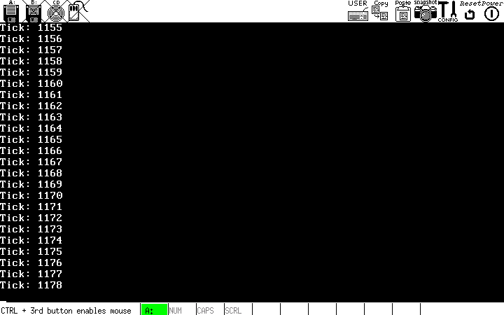
A clock!
Full source code for this tutorial can be found here.